The Reading Realm
September to December 2020
Over 11 weeks, I worked on developing a device using the Internet of Things to be able to control a series of NeoPixel lights using a web browser in order to promote the use of technology to better the fundamental developmental growth of early childhood education. Through this project, I not only learned about the educational benefits that colors bring to a child’s education but also the process of understanding how to wire breadboards and work with Arduino without short-circuiting any equipment. I learned how to use a variety of different tools to reach my goal of working on my device online and how to adapt my code to each program.
Background / The Problem
The idea behind this project was to use it as a teaching tool for children to use in order to learn more about colors and increase their mobility skills.
Due to the increase in technology, it has been harder to engage children in learning if it is not on the screen. Everything that they read now is on the screen, or children want to watch shows instead of learning. In order to make the best of technology, I wanted to develop something that would get children more engaged with the analog items around them. I wanted them to be engaged with the stories they listen to instead of staring at a screen.
What I wanted to develop is something called The Reading Realm. This would be a device that is paired with a story for young children in early education. The story will then allow the children to learn and engage more with the colors within the book. Colored LED lights will be paired with the story where the children will have to change the color of the light or learn how to recognize the different colors that are changing.
Goals and Objectives
The goal of this project is to create a device that is entirely usable over an internet connection with a time frame of 12 weeks. Buttons would be able to control what colors are being displayed on the LED, and a lamp like structure will be created to reduce the intensity of the light itself that is being projected. I will have to learn how to use a breadboard and connect it to the Arduino Mkr 1010. Once a local version is completed and then transferred to IoT, the project will be a success.
Tinkercad

Before actually wiring everything to the Arduino, I used the Tinkercad simulation in order to learn how to code out and hook up all of the hardware before actually performing the task. This allowed me to work without frying the circuit board or purchasing incorrect materials. At first, I had problems trying to learn how to use the Tinkercad simulation. I learned how to organize the wires properly and which resistors to use for the specific lights to work. I originally wanted to use a light bulb in order to show the changes in color. However, I quickly learned first that the light bulb used in the simulator could only turn on and off instead of having different colors.
I then switched to a normal red LED. I first learned how to wire up the LED correctly to the Arduino. When that was successful, I then continued on to the RGB LED which would then be able to allow me the functionality to have color-changing functions. However, when I wanted the buttons to control several colors onto one LED, the colors became less vibrant and more faded. With that in mind and knowing that I would have to go forward on a bigger scale for the project than the small RGB LED, I decided to see if I could learn how to connect the Neopixel LED strips to have a wider range of colors and turn the device into a lamp.
Working Locally
After knowing that the functionality was working on the Tinkercad Simulation, I wired the Arduino onto the breadboard. I connected the resistors and buttons to appropriate pin numbers. I then launched the Arduino sketch editor in order to implement the code into the Arduino. However, I ran into a few problems.
The first problem was with the editor itself. I had the desktop editor downloaded onto my computer and tried using that to implement the code. However, it consistently brought up an error saying that it could not detect the Arduino that I had plugged into the computer. After a long time trying to debug, I then decided to use the web browser editor for Arduino. By using the web browser editor, it was able to detect the Arduino that was plugged in, allowing the code to be implemented.
The second problem that I ran into was that the code that was used in the simulator was not working 100% when implemented in the local Arduino project. From here, I had to learn how to manipulate different parts of the code in order to allow the LED lights to turn on and function when clicking onto the buttons.
Online
When LED lights and the buttons finally worked locally, it was time to move everything to Arduino’s IoT.
The first problem I faced dealt with connecting the Arduino over the internet. The way that my internet connection works in my apartment is that the MAC address needs to be obtained to register it through a system, allowing the device to use the apartment’s internet connection. There was no MAC address on the Arduino or the box of the Arduino. I soon learned that I would have to implement code into the Arduino in order to draw out its MAC address. From understanding that, I found the code that would allow me to see the MAC address of the Arduino through the monitor on the Arduino sketch editor.
#include <SPI.h>
#include <WiFiNINA.h>

void setup() {
  //Initialize serial and wait for port to open:
  Serial.begin(9600);
  while (!Serial) {
    ; // wait for serial port to connect. Needed for native USB port only
  }

  // check for the WiFi module:
  if (WiFi.status() == WL_NO_MODULE) {
    Serial.println("Communication with WiFi module failed!");
    // don't continue
    while (true);
  }

  String fv = WiFi.firmwareVersion();
  if (fv < WIFI_FIRMWARE_LATEST_VERSION) {
    Serial.println("Please upgrade the firmware");
  }

  // print your MAC address:
  byte mac[6];
  WiFi.macAddress(mac);
  Serial.print("MAC: ");
  printMacAddress(mac);
}

void loop() {
  // scan for existing networks:
  Serial.println("Scanning available networks...");
  listNetworks();
  delay(10000);
}

void listNetworks() {
  // scan for nearby networks:
  Serial.println("** Scan Networks **");
  int numSsid = WiFi.scanNetworks();
  if (numSsid == -1) {
    Serial.println("Couldn't get a wifi connection");
    while (true);
  }

  // print the list of networks seen:
  Serial.print("number of available networks:");
  Serial.println(numSsid);

  // print the network number and name for each network found:
  for (int thisNet = 0; thisNet < numSsid; thisNet++) {
    Serial.print(thisNet);
    Serial.print(") ");
    Serial.print(WiFi.SSID(thisNet));
    Serial.print("\tSignal: ");
    Serial.print(WiFi.RSSI(thisNet));
    Serial.print(" dBm");
    Serial.print("\tEncryption: ");
    printEncryptionType(WiFi.encryptionType(thisNet));
  }
}

void printEncryptionType(int thisType) {
  // read the encryption type and print out the name:
  switch (thisType) {
    case ENC_TYPE_WEP:
      Serial.println("WEP");
      break;
    case ENC_TYPE_TKIP:
      Serial.println("WPA");
      break;
    case ENC_TYPE_CCMP:
      Serial.println("WPA2");
      break;
    case ENC_TYPE_NONE:
      Serial.println("None");
      break;
    case ENC_TYPE_AUTO:
      Serial.println("Auto");
      break;
    case ENC_TYPE_UNKNOWN:
    default:
      Serial.println("Unknown");
      break;
  }
}


void printMacAddress(byte mac[]) {
  for (int i = 5; i >= 0; i--) {
    if (mac[i] < 16) {
      Serial.print("0");
    }
    Serial.print(mac[i], HEX);
    if (i > 0) {
      Serial.print(":");
    }
  }
  Serial.println();
}
The Second Problem I faced was understanding how to implement the code to allow a button to function across IoT to turn the LED lights on and off, and also changing the color. I thought that the code was to be implemented within the loop, but found out that the code was supposed to be implemented in the on change function. After many trials and errors, the buttons were created in order to change the colors of the Neopixel LEDs.
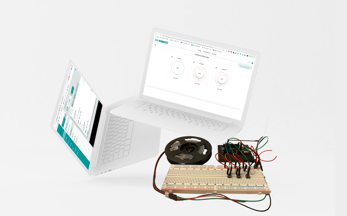
During this process, I able to successfully understand how to not only build an IoT device but understand how to code using Arduino. I was able to figure out how to manipulate code on a simulator, and also adapt to a local version of the device. When I transferred from local code to IoT code, it took a while to adjust to but learned about what mistakes were being made in the online version.
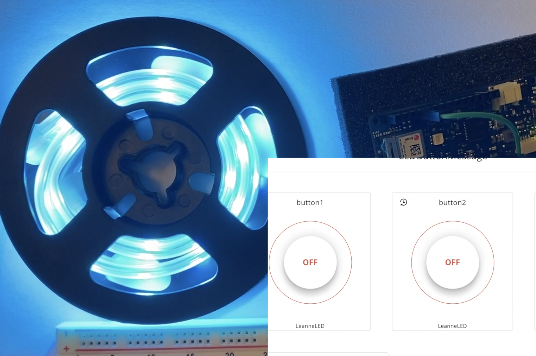
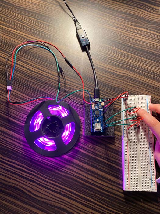
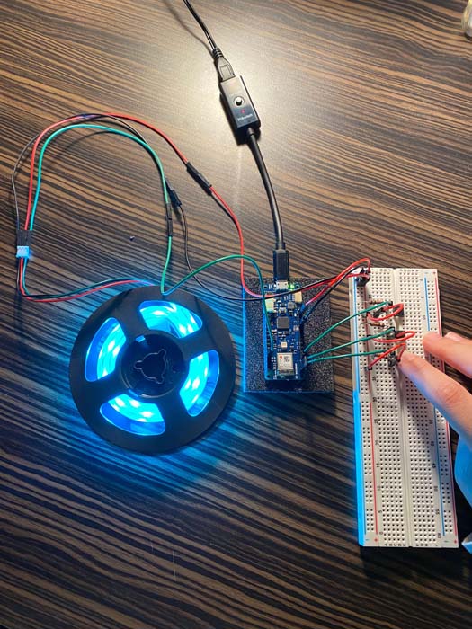
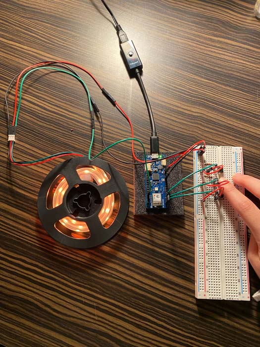
The final design of the Reading Realm consists of three buttons on a dashboard using Arduino’s IoT. Two of the buttons allow a change in the color of the Neopixel LEDs while a third button allows the color of the LEDs to completely turn off.
The results of this project were a success. I was able to develop a fully online controlled Neopixel LED light. I consider this as a success because, at each stage of building this device, it was functioning correctly after debugging numerous amounts of times.
In the future, I would love to go forth to implement a projector that connects to the device to return back to my original idea of The Reading Realm. The buttons would be color-coded while a projection will project an image or a series of colors that the audience has to look at. The user will have to click on the corresponding colored button to match the projection. The projection is paired with a children’s book in order to develop recognition, reading, and listening skills. This enables an interactive learning experience for the user to enjoy when learning about colors and reading/listening.